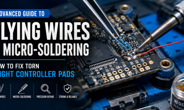
A torn solder pad can turn a normal FPV build into a frustrating repair project. One moment, you are replacing a receiver, camera, motor wire, or video transmitter. The next moment, the copper pad lifts away from the flight controller and remains attached to the wire.
For a new builder, the damage may look permanent. The pad is missing, solder no longer sticks to the original location, and the component cannot be connected in the usual way. However, many torn pads can be repaired without replacing the entire flight controller.
The solution is often a flying wire repair, also known as a jumper-wire or bodge-wire repair. Instead of reconnecting the wire to the missing pad, the technician identifies another point on the same electrical circuit and creates a new connection using a thin insulated wire.
This type of repair requires patience, magnification, controlled heat, and a clear understanding of the circuit. It is not simply a matter of placing more solder over the damaged area. The original pad must first be examined to determine where it was electrically connected.
This guide explains how FPV pilots and hardware makers can diagnose torn pads, select appropriate Micro-Soldering tools, install a Soldering Jump Wire, protect the repaired area with UV Curing Solder Mask, and test the flight controller safely before returning the drone to the air.
Why Flight Controller Solder Pads Tear
A solder pad is a small area of exposed copper attached to the printed circuit board. It provides a location where wires, connectors, and surface-mount components can be soldered.
Pads normally remain securely bonded to the board, but they can separate when exposed to excessive heat or mechanical force.
One common cause is pulling a wire before the solder has completely melted. The solder joint may look soft on the surface while the lower part remains attached. When the wire is lifted, it pulls the copper pad away from the board.
Other common causes include:
- Using excessive soldering temperature
- Heating the pad for too long
- Repeatedly soldering and desoldering the same connection
- Moving the wire while the solder is cooling
- Using a soldering tip that is too small
- Applying force to a wire with no strain relief
- Crashing the drone and pulling wires from the board
- Removing conformal coating too aggressively
- Scraping the PCB with sharp metal tools
Receiver, camera-control, UART, buzzer, LED, and small 5V pads are especially vulnerable because they are small and may be located close to delicate traces and components.
Larger battery and motor pads can also be damaged. However, these connections carry much more current, so they require a different repair strategy than a low-current signal pad.
First Determine Whether the Board Is Repairable
Do not immediately start scraping the flight controller after discovering a missing pad. The first step is determining the extent of the damage.
Disconnect the LiPo battery and remove the flight controller from the drone whenever possible. Working inside a fully assembled frame makes it difficult to inspect the board and increases the risk of damaging nearby wires.
Clean the damaged area with high-purity isopropyl alcohol and inspect it under magnification.
Look for the following:
- Is the pad completely missing or only partially lifted?
- Is the copper trace still visible?
- Has a nearby component moved or cracked?
- Is the PCB surface burnt or discoloured?
- Has the damage reached an internal board layer?
- Are nearby pads still securely attached?
- Did the original wire pull on a via or through-hole?
A partially lifted pad may sometimes be repositioned and secured, but it should not be trusted without additional support. Once the adhesive beneath a pad has failed, normal wire movement may lift it again.
If the board is heavily burnt, cracked through several layers, or missing an entire section of PCB material, replacement may be more practical than repair.
Essential Tools for Torn Pad Repair
A successful flying-wire repair depends heavily on tool control. Standard soldering tools may work for large FPV joints, but they are often unsuitable for exposing tiny traces or attaching wires to component terminals.
Precision Soldering Station
A reliable precision soldering station should maintain a stable temperature and allow the technician to select a tip that matches the size of the repair.
The linked AIFEN A9HD station is listed as a 180W model that supports C115, C210, and C245-style soldering tips. This allows the operator to choose smaller tips for detailed trace work and larger tips for joints that require greater heat transfer.
For most flight-controller signal repairs, a fine C115 or C210-style tip provides better access than a large general-purpose iron. However, the smallest possible tip is not always the best option.
An extremely fine tip may transfer heat poorly. This encourages the operator to raise the temperature or hold the tip on the joint for too long. A slightly larger tip that makes full contact can heat the joint more efficiently and reduce total exposure time.
When searching online, some people accidentally use the phrase “precision soldering staition.” Regardless of the spelling, the most important features are temperature stability, quick thermal recovery, comfortable handling, and access to suitable replacement tips.
Microscope and Fine Hand Tools
A microscope is one of the most important Micro-Soldering tools for repairing torn pads. It helps the technician distinguish between copper traces, exposed fiberglass, solder mask, vias, and nearby component terminals.
The linked 2UUL MC7060-A1 is described as a trinocular stereo microscope with 7X to 60X magnification, adjustable illumination, and support for a separate camera connection.
Stereo optics are useful because they provide depth perception. This allows the technician to judge the position of the soldering tip and jumper wire more accurately.
The workbench should also include:
- Fine straight tweezers
- Curved ESD-safe tweezers
- A sharp micro blade
- A fiberglass scratch pen
- Fine solder wire
- High-quality gel flux
- Solder wick
- Kapton tape
- Isopropyl alcohol
- Lint-free cleaning swabs
- Digital multimeter
- PCB holder
- UV light
The purpose of these tools is not to make the repair faster. Their purpose is to make every movement more controlled.
Insulated Jump Wire
A Soldering Jump Wire creates a new electrical path between the disconnected circuit and another accessible point on the same net.
The linked PHONEFIX product is listed as an ultra-fine wire for motherboard and PCB repair, with options including approximately 0.008mm diameter and a 120-metre spool.
Ultra-fine wire is useful for delicate signal lines because it can be routed around small components without occupying much space. It is suitable for connections such as:
- UART transmit and receive signals
- Camera-control signals
- LED data lines
- Buzzer control signals
- Receiver telemetry
- Small sensor connections
- Low-current logic circuits
However, ultra-fine jump wire should not be used for high-current connections such as VBAT, ESC power, motor output, or main ground connections.
The replacement wire must be able to carry the expected current safely. A signal wire may carry very little current, while a battery or motor connection can carry many amps.
Using an extremely thin wire on a high-current circuit may cause voltage drop, overheating, or complete failure. For larger power pads, use an appropriately sized copper wire and create a mechanically secure connection.
UV Curing Solder Mask
UV Curing Solder Mask is used to secure and insulate the completed repair. It is particularly useful when a trace has been exposed or a fine jumper wire has been attached to a small point.
The mask is applied as a liquid and hardened using ultraviolet light. Once cured, it helps prevent the jumper wire from moving, touching nearby components, or being pulled away from the solder joint.
It should be applied only after the electrical repair has been tested.
Do not cover the connection immediately after soldering. If the repair contains a bridge, weak joint, or incorrect connection, the mask will make it more difficult to inspect and correct.
Use a small amount. A large drop can flow over test points, components, connectors, or areas that may need future repair.
Understanding the Missing Pad’s Electrical Path
The most important part of a torn-pad repair is finding where the original pad was connected.
A pad is rarely an isolated piece of copper. It normally connects to one of the following:
- A visible surface trace
- A nearby via
- A resistor or capacitor
- A processor pin
- A voltage regulator
- A connector terminal
- An internal PCB layer
- Another test pad on the same electrical net
If a visible trace leaves the damaged pad, the repair may be relatively straightforward. A small section of the trace can be exposed and used as a soldering point.
If no trace is visible, the pad may connect through a via or internal layer. In that situation, the technician must identify an alternate electrical point.
Board diagrams, wiring maps, manufacturer documentation, high-resolution board photographs, and continuity testing can all help.
Do not assume that two nearby points are connected because they look similar. Confirm the connection with a multimeter whenever possible.
Use Continuity Mode Carefully
Place one probe on the remaining part of the damaged circuit and use the other probe to test possible alternate points.
A continuity beep may confirm a direct electrical connection. However, some circuits pass through resistors, diodes, or other components and may not produce a simple continuity result.
Resistance and diode-mode readings may be more useful in those cases.
If another working flight controller of the same model is available, compare readings between the damaged board and the functional board.
Step-by-Step Method for Repairing a Torn Signal Pad
The following process is designed primarily for low-current signal pads. High-current power pads require stronger wire and additional mechanical reinforcement.
Step 1: Disconnect All Power Sources
Remove the LiPo battery, USB cable, backup battery, capacitor, and any other connected power source.
Large capacitors may retain energy briefly after the battery is disconnected. Confirm that the board is no longer powered before beginning the repair.
Never perform micro-soldering while the flight controller is connected to a battery.
Step 2: Remove the Damaged Wire
If the wire is still attached to part of the pad, support the wire with tweezers and heat the joint until the solder melts completely.
Do not pull against a solid joint. The goal is to lift the wire using almost no mechanical force.
Clean old solder and flux from the area. This will make the remaining trace easier to inspect.
Step 3: Identify an Alternate Connection Point
Follow the visible trace from the damaged pad. Under magnification, it may lead to a via, resistor, processor-side component, or another accessible pad.
Use the multimeter to confirm that the selected point belongs to the same electrical circuit.
Whenever possible, choose a test pad, via, resistor terminal, or exposed trace rather than soldering directly to a fine-pitch processor pin.
A larger accessible point will create a stronger and more reliable repair.
Step 4: Expose a Small Section of Copper
If the repair will connect directly to a trace, remove a very small amount of solder mask using a micro blade or fiberglass pen.
Work under the microscope and scrape in a controlled direction.
The objective is to reveal enough copper for the jumper wire without thinning or cutting the trace. Exposing a long section is unnecessary and weakens the protection around the circuit.
Stop as soon as clean copper becomes visible.
Step 5: Clean and Pre-Tin the Trace
Apply a small amount of flux to the exposed copper.
Use a clean soldering tip with a tiny amount of solder to pre-tin the trace. The solder should coat the copper without forming a large ball.
If solder does not attach easily, clean the area again and confirm that the solder mask has been completely removed.
Avoid holding the iron on the exposed trace for too long. A thin trace can separate from the PCB if overheated.
Step 6: Prepare the Jumper Wire
Cut a length of jumper wire that can reach the alternate point without being stretched tightly.
A wire that is too short places mechanical tension on both solder joints. A wire that is too long may move around, touch nearby parts, or interfere with board installation.
Remove or burn away only the minimum insulation required at each end. Pre-tin the exposed ends before placing the wire on the board.
Pre-tinning reduces the amount of time the soldering iron must remain on the delicate repair point.
Step 7: Attach the First End
Position the pre-tinned end of the jumper wire over the exposed trace or alternate soldering point.
Hold it in place with fine tweezers. Touch the soldering tip to the joint only long enough to melt the existing solder and connect the wire.
Remove the iron while continuing to hold the wire still. Allow the joint to cool before releasing the tweezers.
Inspect the connection under the microscope. The wire should be attached securely without bridging neighbouring traces or components.
Step 8: Route the Flying Wire Safely
Route the wire along a clear path across the PCB. Avoid passing it directly over sharp component edges, processors, high-temperature regulators, or screw holes.
The wire should not cross areas where the board contacts the drone frame.
Leave a small amount of slack near the joint. The wire should not be stretched like a tight string, but it should not form a large unsupported loop either.
Small spots of UV Curing Solder Mask can later be used to hold the wire at safe points along its route.
Step 9: Connect the External Wire
The other end of the jumper may connect directly to the receiver, camera, video transmitter, GPS, buzzer, or another peripheral.
In some repairs, it is better to create a small reinforced connection point on the board and then attach the external wire there.
The fine jumper wire should not carry mechanical tension from a thick external cable. If a receiver wire moves during maintenance, it could pull the micro-jumper from the trace.
Secure thicker wires to the board or nearby wire bundle so that movement does not reach the repaired joint.
Step 10: Test Before Applying Solder Mask
Use continuity mode to confirm that the repaired connection reaches the correct destination.
Then check for accidental continuity between the repaired line and nearby ground, power, or signal points.
Inspect the board carefully for:
- Solder bridges
- Loose wire strands
- Lifted components
- Excess flux
- Damaged insulation
- Wire contact with sharp surfaces
- Incorrect routing
Power the board through a smoke stopper or current-limited bench supply before reconnecting a full LiPo battery.
If the flight controller has a USB interface, confirm that it connects to the configurator and that the repaired UART, sensor, or peripheral responds normally.
Step 11: Apply UV Curing Solder Mask
Once the electrical connection has passed testing, clean the repair area and allow it to dry.
Apply a small drop of UV Curing Solder Mask over the exposed trace and soldered jumper connection. Use a fine applicator or needle to control the amount.
Cure it using an appropriate UV light according to the material’s instructions.
Additional small spots can be applied along the wire route to provide strain relief. Do not completely bury large areas of the board.
The final repair should remain inspectable and should not cover nearby pads that may be required later.
Repairing Different Types of Torn Pads
Not every flight-controller pad should be repaired in the same way. The electrical load and physical design determine the correct method.
UART, LED and Camera-Control Pads
These are generally low-current signal pads and are good candidates for ultra-fine jumper-wire repair.
Find the next accessible point on the trace, make a short connection, and secure the wire with solder mask.
Keep the wire away from noisy power components when possible, especially when repairing sensitive analog or communication signals.
5V and 9V Output Pads
These pads power receivers, video transmitters, cameras, GPS units, and other peripherals.
Before repairing the pad, determine how much current the connected device requires. Ultra-fine micro-jumper wire may not be appropriate.
An alternate 5V or 9V pad on the same regulated rail may be a safer option. Confirm that the regulator can support the additional load.
Ground Pads
Ground may appear simple because many points on the board connect to ground. However, the replacement connection still needs enough current capacity.
A small signal ground may be moved to another suitable ground pad. Main power ground connections require much larger conductors and strong joints.
Do not rely on a microscopic wire for a high-current ground path.
VBAT and ESC Power Pads
Main battery pads and ESC output connections experience high current, vibration, and significant mechanical stress.
These repairs require appropriately sized wire, large copper contact areas, and strong mechanical reinforcement. A small trace-level jumper is usually not sufficient.
If the PCB has lost a large portion of the copper around a main power pad, replacing the board may be safer than attempting a weak repair.
Through-Hole Pads and Vias
Some flight controllers use plated through-holes for connectors or power wires.
If the copper barrel inside the hole has been damaged, soldering only to the top surface may not restore the connection between PCB layers.
The technician must determine whether the hole connects to internal layers and whether an alternate point can safely replace that connection.
Multilayer damage can be difficult to repair reliably without board documentation.
Common Flying-Wire Repair Mistakes
Soldering to an Unconfirmed Point
The nearest component is not always connected to the missing pad. Use continuity, resistance measurements, or a trusted board diagram before making the repair.
Using Too Much Heat
More heat does not guarantee a better joint. It can lift additional traces, damage nearby components, and melt connectors.
Use flux, a suitable tip, and efficient contact.
Choosing Wire That Is Too Thin
Ultra-fine wire works well for logic signals but should not be used for high-current power circuits.
Select wire according to the current, length, and mechanical demands of the connection.
Failing to Add Strain Relief
A jumper wire may be electrically perfect but mechanically weak. Secure the wire so that external cable movement does not pull directly on the repair point.
Applying UV Mask Before Testing
Solder mask should be the final protective step. Test continuity, isolation, peripheral operation, and board startup before curing material over the connection.
Leaving Flux Residue
Flux can hide solder bridges and make inspection difficult. Clean the area before testing and again before applying protective mask.
Creating a Long Unsupported Wire Route
A long loose wire can move during crashes and vibration. Keep the route controlled and secure it at several safe points.
Testing the Flight Controller After Repair
A repaired flight controller should not be placed directly into a fully powered drone.
Begin with a visual inspection and multimeter checks. Confirm that no power rail has been shorted during the repair.
Connect the board through a smoke stopper or current-limited supply. Watch for abnormal current draw, smoke, heat, or unexpected component behaviour.
Next, connect USB and open the appropriate configuration software. Check that the flight controller is recognised and that its sensors operate normally.
Test the repaired function specifically.
For example:
- Confirm that the receiver communicates correctly
- Check UART input and output activity
- Verify camera control
- Test buzzer operation
- Confirm LED data output
- Check GPS communication
- Verify video transmitter control
- Confirm stable regulated voltage
After installing the board in the drone, inspect the jumper-wire route again. Make sure it is not trapped beneath a mounting screw, pressed against carbon fibre, or stretched by connected cables.
Perform the first battery test without propellers. Arm the drone only after confirming that the flight controller, receiver, video system, motors, and failsafe settings work correctly.
The first flight should be short and controlled. Reinspect the repair afterward for movement, heat, or damage.
How to Prevent Torn Pads in Future Builds
Preventing pad damage is much easier than repairing it.
Always apply flux before desoldering a wire. Heat the joint until the solder is completely liquid and lift the wire without pulling.
Use the correct soldering tip. A large pad requires enough thermal mass to melt the joint quickly. A small signal pad requires a controlled tip that does not touch neighbouring components.
Pre-tin both the pad and wire before joining them. This reduces heating time and creates a cleaner connection.
Support wires mechanically. Receiver, GPS, camera, and video-transmitter wires should not pull directly on flight-controller pads.
A small cable tie, adhesive mount, or controlled spot of flexible support material can reduce stress during crashes and maintenance.
Avoid repeatedly moving components between pads. If a build is tested frequently, temporary connectors or test leads may reduce repeated soldering.
Finally, practise on damaged or unused boards before attempting repairs on an expensive flight controller. Micro-soldering control improves through repetition.
Frequently Asked Questions
Can every torn flight-controller pad be repaired?
No. Many signal pads can be restored using a jumper wire, but severe multilayer damage, burnt PCB material, cracked boards, and destroyed high-current sections may not be safely repairable.
The cost and reliability of the repair should be compared with the price of a replacement board.
What is a flying wire in motherboard repair?
A flying wire is an added conductor used to replace a damaged trace, missing pad, or broken circuit connection.
It connects the original circuit to another electrically equivalent point. It is also commonly called a jumper wire or bodge wire.
Can I solder the wire directly to a processor pin?
It may be technically possible in some cases, but it is usually better to find a larger accessible point such as a resistor terminal, via, or test pad.
Processor pins are extremely small and easy to bridge or damage.
Is ultra-fine jump wire suitable for battery-pad repair?
No. Ultra-fine motherboard repair wire is designed primarily for low-current signals.
Battery, motor, main ground, and other power connections require wire with enough current-carrying capacity and mechanical strength.
Why does solder not stick to the exposed trace?
The copper may still be covered with solder mask, contamination, corrosion, or damaged material.
Clean the area, expose fresh copper carefully, apply flux, and use a clean tinned tip. Avoid increasing the temperature excessively.
Is UV Curing Solder Mask the same as glue?
It provides insulation and mechanical support, but it should not be treated as a replacement for a correct solder joint.
The electrical connection must be secure before the mask is applied.
Should I use a hot-air station for a torn pad?
Most simple jumper-wire repairs can be completed with a fine soldering iron.
Hot air may be useful when replacing nearby surface-mount components, but it can also move small parts or cause additional pad damage if used incorrectly.
Turn a Damaged Pad into a Reliable Repair
A torn flight-controller pad does not always mean the end of the board. With accurate diagnosis and careful micro-soldering, many damaged signal connections can be restored using a properly routed flying wire.
The most important step is understanding where the original pad was connected. Once the correct electrical point has been identified, the technician can expose a small section of copper, attach a suitable jumper wire, test the circuit, and protect the finished repair with UV Curing Solder Mask.
Good tools make the process more controlled, but patience and measurement are equally important. A stable soldering station, microscope, fine tweezers, multimeter, appropriate wire, and clean work area allow FPV builders to repair damage that would be almost impossible to handle with a basic soldering kit.
Treat every repair as both an electrical and mechanical task. The connection must conduct correctly, survive vibration, remain insulated, and avoid placing stress on the flight controller.
By following a careful workflow, FPV pilots can save valuable hardware, improve their micro-soldering skills, and return damaged builds to the air with greater confidence.